
TB 9-6625-152-24
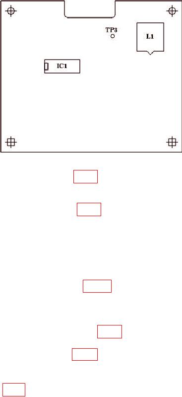
Figure 4. A 10/1 Board.
(3) Attach extension wire to TP3 (fig. 4).
NOTE
On early boards TP3 did not exist. If TP3 is nonexistent attach
extension wire to IC1 pin 7 (fig. 4).
(4) Route wire through hole in RF lid and place RF lid back in position. Secure lid
with two screws.
(5) Connect oscilloscope and multimeter to extension wire. Set multimeter for DC
measurement.
(6) Press TI [RX TEST].
(7) Slowly advance L1 adjuster (fig. 4), observing waveform on oscilloscope.
(9) Continue advancing L1 adjuster (fig. 4) until lock is lost and multimeter
indication increases further.
(10) Slowly unscrew L1 adjuster (fig. 4), observing oscilloscope waveform frequency
decreasing, until lock is regained when frequency becomes zero.
lock to 90 MHz, in the middle of its capture range.
(13) Remove TI RF lid and remove extension wire.
(14) Replace and secure TI RF lid.
(15) Press TI [MEM] key and recall memory 01.
33