
TB 9-6625-152-24
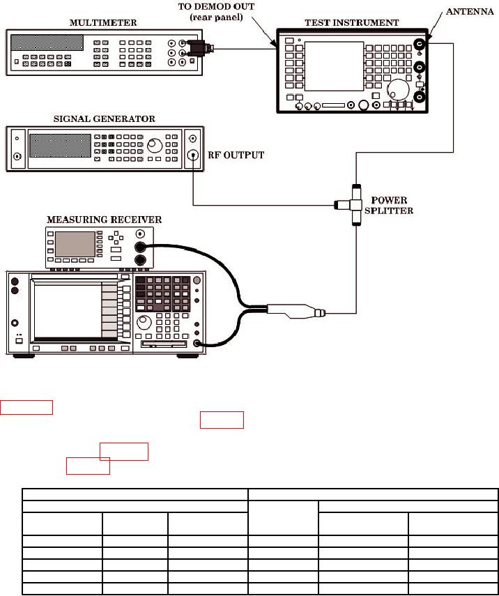
Figure 3. AM Modulation Analyzer Connection.
(5) Adjust signal generator AM depth for first value listed in AM Depth column of
table 20 as indicated on measuring receiver. If TI displayed AM LEVEL indication is not
within limits specified in first row of table 20 for specific model, perform b below.
(6) Repeat technique of (2) (f), (3) and (5) above for signal generator outputs and TI
settings listed in table 20. If TI displayed AM LEVEL indications are not within limits
specified in table 20 for specific model, perform b below.
Table 20. AM Modulation Analyzer 70% Depth.
Signal generator
Test instrument
Output
Indication limits
Mod rate
AM Depth
Model 2947 (%)
Model 2947A (%)
(Hz)
(Hz)
(Hz)
(%)
500 k
1k
70
500 k
61 to 79
66 to 74
500 M
1k
70
500 M
61 to 79
66 to 74
1050 M
1k
70
1050 M
61 to 79
66 to 74
100 M
400
70
100 M
61 to 79
63 to 77
100 M 1
100 M
10 k
70
61 to 79
63 to 77
Set TI IF filter to 300 kHz and AF filter to 50 kHz.
1
28