
TB 9-6625-152-24
(c) Press Tx TEST, [Mod Meter] and [AM/FM/SSB] to select FM.
(d) Press Tx TEST, [Mod Meter], [IF Filter] and [30 kHz].
(e) Press AF TEST, [AF Filter] and [0.3 to 3.4 kHz].
(f) Press Tx TEST, [Tx Freq], 5.5, MHz keys.
(2) Set signal generator for a 5.5 MHz, 6 dBm output with FM modulation of 20 kHz
deviation at a 1 kHz modulation rate.
(3) Configure measuring receiver to measure FM deviation with 50 Hz high pass
filter, 15 kHz low pass filter and detector to Peak/2.
(4) Adjust signal generator FM deviation for first value listed in FM Deviation
column of table 22 as indicated on measuring receiver. If TI displayed FM LEVEL
indication is not within limits specified in first row of table 22 for specific model, perform b
below.
(5) Repeat technique of (1) (f), (2) and (4) above for signal generator outputs and TI
settings listed in table 22. If TI displayed FM LEVEL indications are not within limits
specified in table 22 for specific model, perform b below.
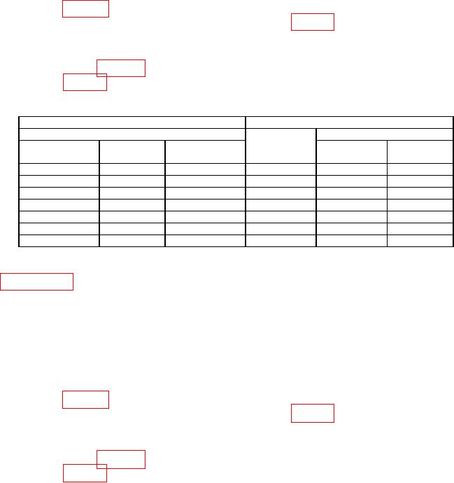
Table 22. FM Modulation Analyzer 1 kHz Modulation Rate.
Signal generator
Test instrument
Output
Indication limits (kHz)
Mod rate
FM deviation
(MHz)
(MHz)
(kHz)
(kHz)
Min
Max
5.5
1
20
5.5
18.8
21.2
100
1
20
100
18.8
21.2
500
1
20
500
18.8
21.2
1000
1
20
1000
18.8
21.2
100
1
50
100
47.0
53.0
100
1
75
100
70.5
79.5
100
1
1
100
0.94
1.06
(6) For model model 2947A proceed to (7) below.
For model 2947 proceed to
paragraph 22 below.
(7) Set measuring receiver high pass filter to off and low pass filter to 3 kHz.
(8) Press TI AF TEST, [AF Filter] and [3 kHz LP].
(9) Press Tx TEST, [Tx Freq], 5.5, MHz keys.
(10) Set signal generator for a 5.5 MHz, 6 dBm output with FM modulation of 20 kHz
deviation at a 100 Hz modulation rate.
(11) Adjust signal generator FM deviation for first value listed in FM Deviation
column of table 23 as indicated on measuring receiver. If TI displayed FM LEVEL
indication is not within limits specified in first row of table 23 for specific model, perform b
below.
(12) Repeat technique of (9) through (11) above for signal generator outputs and TI
settings listed in table 23. If TI displayed FM LEVEL indications are not within limits
specified in table 23 for specific model, perform b below.
30