TB 9-6625-2056-24
(5) Set TRIGGERING LEVEL control to 0 (midrange) and TRIGGERING
illuminated, perform b (1) below.
(6) Set TRIGGERING SLOPE switch to - (minus).
If oscilloscope display is
unstable, perform b (2) below.
(7) S e t T R I G G E R I N G S L O P E s w i t c h b a c k a n d f o r t h b e t w e e n + ( p l u s )
b. Adjustments
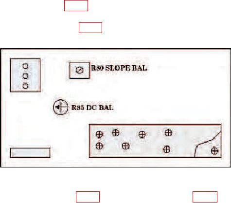
(1) Adjust R85 DC BAL (fig. 1) until oscilloscope display is stable and TRIG'D light
is illuminated (R).
(2) Adjust R80 SLOPE BAL (fig. 1) until oscilloscope display is stable (R).
Figure 1. Test instrument - right view.
display remains stable when TRIGGERING SLOPE switch is set to + (plus) and
- (minus).
9. Sweep Calibration, Length, and Positioning
a. Performance Check
(1) Set TIME/DIV switch to 1 ms and press TRIGGERING MODE AUTO pushbutton.
(2) Set oscilloscope for 1 ms MARKER output.
(3) Adjust vertical amplifier controls for a convenient display centered
vertically on oscilloscope.
(4) Adjust SWP CAL (front panel) for exactly 1 time marker per division over
center 8 divisions of oscilloscope graticule. If necessary, adjust POSITION control to align
time markers with graticule lines.

