
TB 9-6625-2134-24
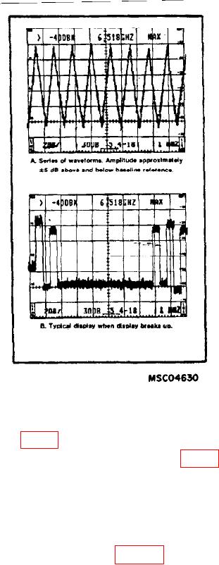
Figure 14. Typical Response Displays When Adjusting
Compensation of Baseline Leveling Circuits.
(190) Adjust R1069 (fig. 12) to center display on crt.
(191) Adjust R1061 (low) through R1013 (high) (fig. 12) for an optimum straight
line display on crt.
(192) Repeat technique of (160) through (180) above and push POWER switch to
off.
(193) Remove and reinstall log amplifier board on service kit extender board and
pull POWER switch to on.
(194) Connect equipment as shown in figure 15 below.
28