
TB 9-6625-2134-24
(153) Adjust R1013 (fig. 8) for an indication of -0.25 V.
(154) Press FREQUENCY RANGE pushbutton until 5.4-18 GHz is shown on crt.
(155) Adjust R1022 (fig. 8) for -0.25 V indication on multimeter.
(156) Press FREQUENCY RANGE pushbutton until 15-21 GHz shows on crt.
(157) Adjust R1026 (fig. 8) for -0.25 V indication on multimeter.
(158) Disconnect multimeter.
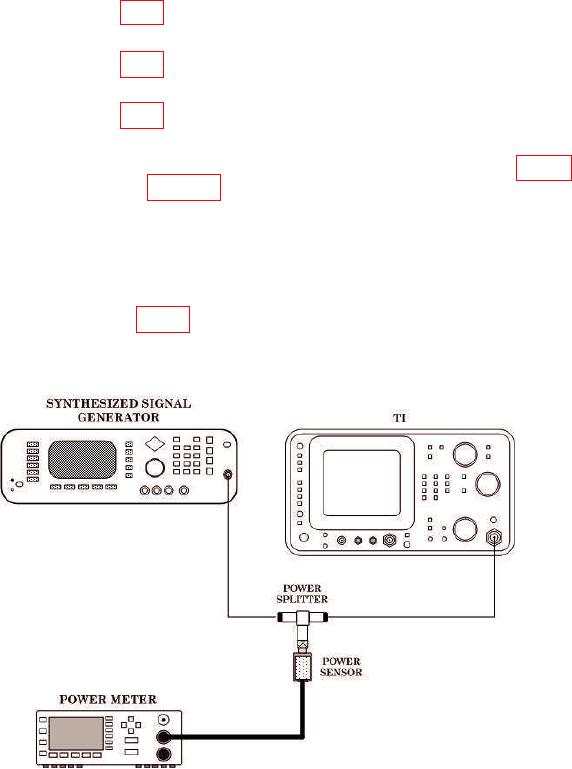
(159) Push POWER switch to off and remove video processor board (fig. 12) and
connect equipment as shown in figure 11.
NOTE
Technique of (160) through (192) need only be performed if
5.4-18 GHz (band 4) frequency response does not meet
specifications.
(160) Remove P3035 (fig. 12) from processor board.
Figure 11. Baseline Leveling - Equipment Setup.
24