
TB 9-6625-2134-24
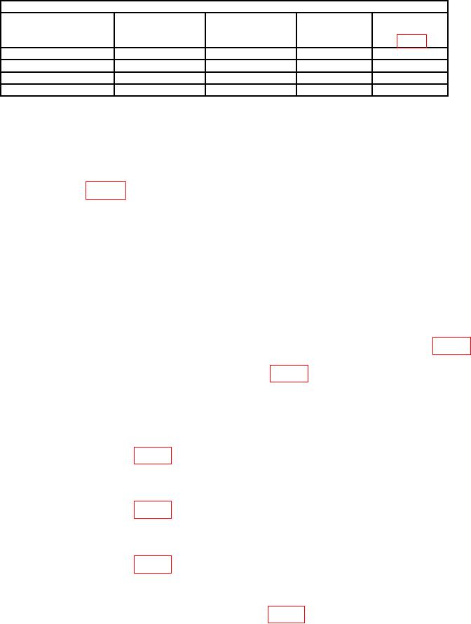
Table 4. Filter Leveling.
Test instrument
FREQUENCY
RESOLUTION
Adjustments
SPAN/DIV
FREQUENCY
settings
settings
settings
Filter
500
kHz
1
MHz
100 MHz
1
MHz
R1065
20
kHz
10
kHz
100 MHz
10
kHz
R3035
5
kHz
1
kHz
100 MHz
1
kHz
R3025
500
Hz
100
Hz
100 MHz
100
Hz
R3015
(261) Connect power meter input to variable attenuator and connect variable
attenuator to signal generator RF output.
(262) Set variable attenuator switches for 0 dB and adjust signal generator for a
10 MHz signal at -20 dBm indication on power meter.
(263) Disconnect power meter from variable attenuator and connect variable
attenuator to J693 (fig. 20).
(264) Position controls as listed in (a) through (e) below:
(a) REFERENCE LEVEL control to -30 dBm.
(b) MIN RF ATTEN control to 0 dB.
(c) FREQUENCY SPAN/DIV control to 1 MHz.
(d) RESOLUTION BANDWIDTH control to 100 kHz.
(e) VERT DISPLAY 2 dB/DIV pushbutton on.
(265) Set variable attenuator switches to 15 dB.
(266) Adjust AMPL CAL control (front panel) fully ccw and adjust R2031 (fig. 18)
amplitude is greater than 5 divisions, adjust R2038 (fig. 18) for a 5 division indication on
crt. If less than 5 divisions, adjust AMPL CAL (front panel) for a 7 division display from
bottom of crt.
(267) Set variable attenuator switches to 25 dB.
(268) Adjust REFERENCE LEVEL control for -40 dBm.
(269) Adjust R3035 (fig. 20) for a 7 division display on crt.
(270) Set variable attenuator switches to -35 dB.
(271) Adjust REFERENCE LEVEL control for -50 dBm.
(272) Adjust R2023 (fig. 20) for a 7 division display on crt.
(273) Set variable attenuator switches to -55 dB.
(274) Adjust REFERENCE LEVEL control for -70 dBm.
(275) Adjust R2060 (fig. 20) for a 7 division display on crt.
(276) Repeat technique of (265) through (275) above for -45, -55, -65, and -75 dBm
input levels and note that each maintains the 7 division signal.
(277) Disconnect signal generator from J693 (fig 17).
36