
TB 9-6625-2134-24
(302) Position controls as listed in (a) through (h) below:
(a) VERTICAL DISPLAY 2 dB/DIV pushbutton on.
(b) REFERENCE LEVEL control to -20 dBm.
(c) FREQUENCY SPAN/DIV control to 10 MHz.
(d) RESOLUTION BANDWIDTH control to 1 MHz.
(e) TIME/DIV switch to AUTO.
(f) DIGITAL STORAGE (option 02) VIEW A pushbutton on.
(g) DIGITAL STORAGE (option 02) VIEW B pushbutton on.
(h) FREQUENCY RANGE pushbutton to 1.7 - 5.5 GHz.
(303) Connect synthesized signal generator to RF INPUT. Adjust source for
-20 dBm signal equal in frequency as recorded in frequency response performance check.
NOTE
If power meter is used to monitor signal level, connect the
power meter sensor at the RF INPUT.
(304) Adjust FREQUENCY control to
center
signal
while
adjusting
FREQUENCY SPAN/DIV to 500 kHz or 1 MHz.
(305) Adjust R3034 (fig. 18) for a full-screen display.
(306) Repeat technique of (303) through (305) above for remaining coaxial band
settings (checked in the frequency response check) and make corresponding adjustments
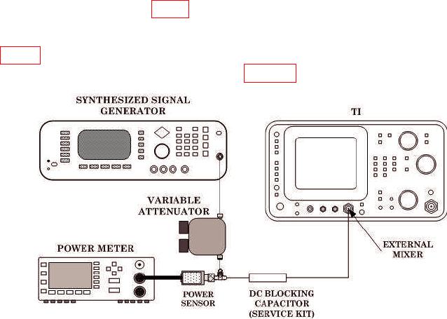
(307) Connect equipment as shown in figure 24.
Figure 24. Band Leveling - Equipment Setup.
40