TB 9-6625-2134-24
(308) Remove VR modules #1 and #2 and reinstall using service kit extender board.
(309) Position controls as listed in (a) through (d) below:
(a) FREQUENCY RANGE pushbutton to 18 - 26 GHz.
(b) FREQUENCY SPAN/DIV control to 200 MHz.
(c) AUTO RESOLUTION pushbutton to on.
(d) REFERENCE LEVEL control to -30 dBm.
(310) Adjust synthesized signal generator for 2072 MHz and -60 dBm output
indication on power meter.
(311) Adjust 3024 (fig. 18) for a full-screen display (top of crt).
(312) Repeat technique of (310) and (311) above for TI settings and adjustments
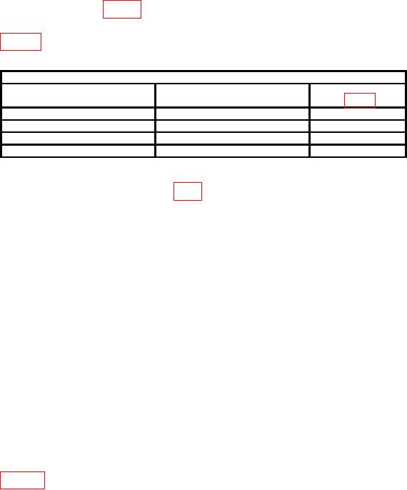
listed in table 5.
Table 5. External Mixer Band Leveling Adjustments.
Test instrument
Input level
Gain adjustments
FREQUENCY RANGE
settings
(dBm)
20-40
-60
R3026
40-90
-60
R3032
60-90
-60
R3029
90-140
-60
R3028
(313) Push POWER switch to off. Remove extender board and reinstall VR
modules. Remove preselector driver board (fig. 8) and reinstall using service kit extender board.
(314) Connect multimeter between center tap of PEAKING potentiometer (located
on bottom side) and ground.
(315) Adjust PEAKING control for 0 V indication on multimeter. If index on
PEAKING control is not aligned with mark on front panel, loosen screw on control and
position mark until aligned.
(316) Disconnect multimeter and connect CAL OUT to RF INPUT.
(317) Position controls as listed in (a) through (d) below:
(a)REFERENCE LEVEL control to 30 dBm.
(b)FREQUENCY SPAN/DIV control to 20 MHz.
(c) AUTO RESOLUTION pushbutton on.
(d) FREQUENCY RANGE pushbutton to 1.7 - 5.5 GHz.
NOTE
Press VIDEO FILTER NARROW pushbutton if needed to
view marker.
(318) Adjust FREQUENCY control to center the 2.1 GHz marker on crt. Adjust
R1031 (fig. 25) for maximum response of 2.1 GHz marker and press DEGAUSS
pushbutton.
41

