
TB 9-6625-2134-24
(2) Adjust synthesized signal generator for a 4 GHz signal at 0 dBm indication on
power meter.
(3) Set variable attenuator switches to 30 dB.
(4) Position TI controls as listed in (a) through (f) below:
(a) FREQUENCY RANGE control to 3.0 - 7.1 GHz.
(b) FREQ SPAN/DIV control to 200 MHz.
(c) AUTO RESOLUTION pushbutton on.
(d) REFERENCE LEVEL control to -30 dBm.
(e) VERTICAL DISPLAY 10 dB/DIV pushbutton on.
(f) TIME/DIV switch to AUTO.
(5) Center display on crt with FREQUENCY control while decreasing FREQ
SPAN/DIV control to 20 kHz.
(6) Position controls as listed in (a) through (c) below:
(a) RESOLUTION BANDWIDTH control to 100 kHz.
(b) VERTICAL DISPLAY 2 dB/DIV pushbutton on.
(c) VIDEO FILTER NARROW pushbutton to on.
(7) Adjust synthesized signal generator output to set signal peak to a graticule
reference level and press DIGITAL STORAGE SAVE A pushbutton to on.
(8) Adjust REFERENCE LEVEL control for -20 dBm indication on crt and
decrease variable attenuator by 10 dB.
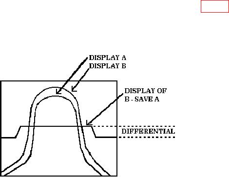
(9) Press DIGITAL STORAGE B-SAVE A pushbutton to on to obtain the
differential. Differential indicated will not exceed 0.3 dB plus insertion loss (fig. 27).
(10)Press DIGITAL STORAGE SAVE A and B - SAVE A pushbuttons to off.
(11) Repeat technique of (7) through (10) above for -20 dB and -10 dB. Differential
indication on crt will not exceed 0.6 dB plus insertion loss.
Figure 27. RF Attenuator Accuracy.
46