
TB 9-6625-2134-24
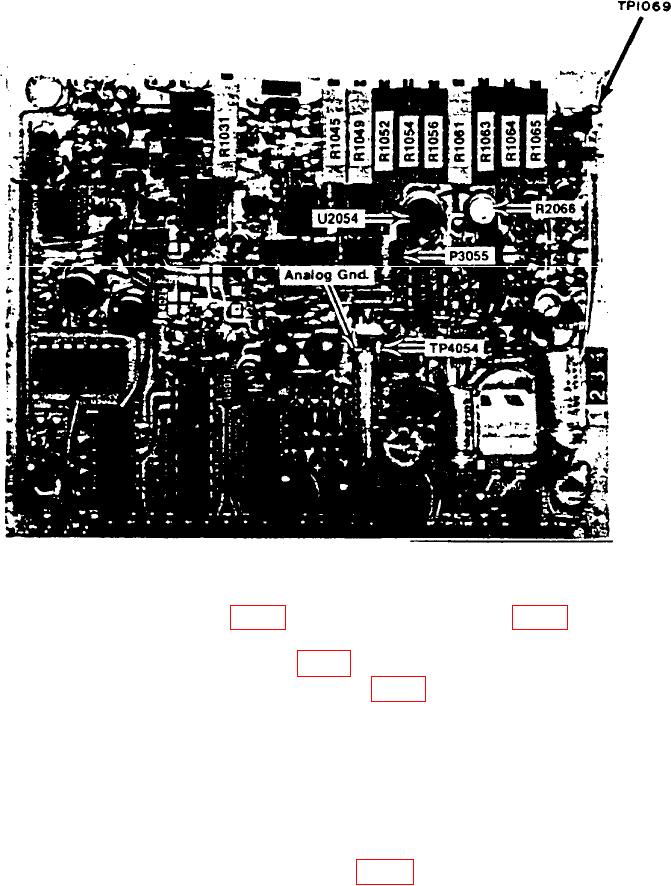
Figure 25. Preselector Drive - Adjustments and Test Point Locations.
(319) Readjust FREQUENCY control to center 2.1 GHz marker, if needed.
response of 2.1 GHz marker.
(321) Remove lead from TP1069 (fig. 25) and press DEGAUSS pushbutton.
(322) Peak 2.1 GHz marker with R1049 (fig. 25) and disconnect CAL OUT from
RF INPUT.
(323) Connect microwave comb generator to REFERENCE INPUT and adjust
RF LEVEL control to -10 dBm.
(324) Adjust FREQUENCY control for a center frequency of 5.5 GHz and
center 5.5 GHz marker on crt.
(325) Press DEGAUSS pushbutton and recenter 5.5 GHz marker from microwave
comb generator.
(326) Peak 5.5 GHz marker with R1065 (fig. 25).
42