
TB 9-6625-2134-24
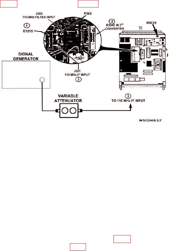
(278) Connect signal generator to 110 MHz filter input J365 110 MHz FILTER
INPUT (fig. 21), using equipment setup in figure 15 (J365 instead of J621).
Figure 21. IF Gain - Adjustment Locations.
(279) Pull POWER switch to on.
(280) Position controls as listed in (a) through (c) below:
(a) FREQUENCY control to 110 MHz.
(b) REFERENCE LEVEL control to -20 dBm.
(c) RESOLUTION BANDWIDTH control to 100 kHz.
(281) Adjust signal generator for 110 MHz and -21.5 dBm signal output, with
variable attenuator set to 0 dB.
(282) Adjust FREQUENCY SPAN/DIV control to 100 kHz while centering
signal on crt.
(283) Adjust signal generator output for a 7 division signal reference level and
record signal generator output.
(284) Press POWER switch to off.
(285) Disconnect signal generator from J365 110 MHz FILTER INPUT and connect
to J321 110 MHz IF INPUT on the 100 MHz IF amplifier (fig. 21).
(286) Reconnect P365 to J365 (fig. 21) and set attenuator switches to 21 dB.
(287) Pull POWER switch to on.
37