
TB 9-6625-2134-24
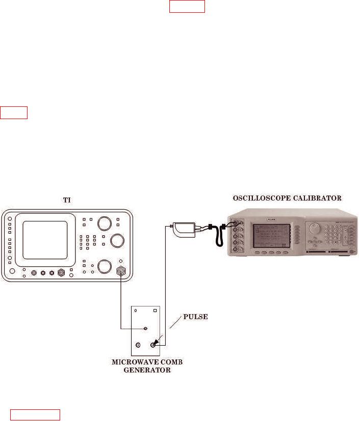
(18) Connect equipment as shown in figure 30 below.
(19) Set oscilloscope calibrator to 2 ms markers.
(20) Adjust REFERENCE LEVEL control to -20 dBm and FREQUENCY
SPAN/DIV control for 100 MHz.
(21) Adjust FREQUENCY control toward 500 MHz and adjust FREQUENCY
SPAN/DIV control for 500 kHz. Adjust FREQUENCY control to center a marker on crt.
Accuracy will be within 5 percent over center 8 division.
(22) Adjust RESOLUTION BANDWIDTH control to 1 kHz.
(23) Adjust FREQUENCY SPAN/DIV control and oscilloscope calibrator as listed in
table 6 for 50, 20, and 10 kHz settings. FREQUENCY SPAN/DIV accuracy will be within
5 percent over center 8 divisions.
(24) Repeat technique of (21) above with RESOLUTION BANDWIDTH control
adjusted to 100 Hz and oscilloscope calibrator adjusted for 50 ms markers. Check
FREQUENCY SPAN/DIV setting of 5, 2, and 1 kHz and 500 Hz. Accuracy will be within
5 percent over center 8 divisions.
Figure 30. Frequency Span/Div - Equipment Setup.
b. Adjustments. If an out-of-tolerance condition is noted, perform adjustments listed
in paragraph 8 b above.
56