
TB 9-6625-2134-24
27. Power Supply
NOTE
Do not perform power supply check if all other parameters are
within tolerance.
a. Performance Check
(1) Connect multimeter to TP1046 (+15V) test point (fig. 2) and chassis ground.
Multimeter will indicate between +14.84 and +15.13 V.
(2) Repeat technique of (1) above for supply voltages at test points listed in table 11.
If an out-of-tolerance condition is noted, perform b below.
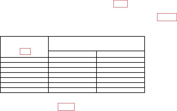
Table 11. Power Supply Voltage.
Test instrument
indications
test points
(V)
Min
Max
TP1011
+9.0
+10.0
TP1036
-4.95
-5.05
TP1035
-14.90
-15.50
TP1044
+4.85
+5.10
TP1047
+16.8
+18.6
TP1048
+95
+105
TP1052
+280
+310
b. Adjustments. Adjust R6028 (fig. 21) until all power supply voltages are within
tolerance. (Resistor R6028 is located under screw on the bottom side.)
28. Final Procedure
a. Deenergize and disconnect all equipment and reinstall protective cover on TI.
b. Annotate and affix DA label/form in accordance with TB 750-25.