
TB 9-6625-2139-24
b. Adjustments
(1) Disconnect oscilloscope calibrator CHAN 1 from TI CH 1.
(2) Set CH 1 AC GND DC switch to AC.
(3) Set CH 1 VOLTS/DIV switch to 50m.
(4) Adjust CH 1 POSITION control to position trace on center horizontal
graticule line.
(5) Set CH 1 VOLTS/DIV switch to 5m.
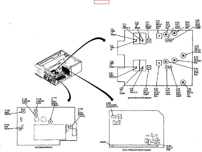
(6) Adjust R10 CH1 STEP BAL (fig. 1) to position trace on center horizontal
graticule line.
Figure 1. Adjustment locations.
(7) Repeat (3) through (6) above for minimum trace shift when setting CH 1
VOLTS/DIV switch from 50m to 5m.
(8) Adjust CH 1 POSITION control to position trace on center horizontal
graticule line.
(9) Set CH 1 VOLTS/DIV switch to 2m.