
TB 9-6625-2139-24
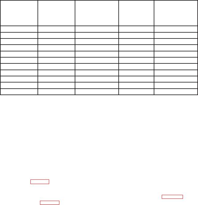
Table 4. CH 2 Vertical Deflection
Oscilloscope
Oscilloscope
calibrator
Test instrument
Test instrument
calibrator
Test instrument
Err display
VOLTS/DIV
divisions of vertical
VOLTAGE
adjustments
indications
deflection
switch settings
output settings
(r %)
b(42) thru (82)
2
m
10 mV
5
2
5
m
20
mV
4
2
10
m
50
mV
5
2
20
m
0.1 V
5
2
50
m
0.2 V
4
2
0.1
0.5 V
5
2
0.2
1
V
5
2
0.5
2
V
4
2
1
5
V
5
2
2
10
V
5
2
5
20
V
4
2
(13) Connect oscilloscope calibrator CHAN 1 to TI CH 1 using a 50 :
feedthrough termination.
(14) Position controls as listed in (a) through (c) below:
(a) VERTICAL MODE CH 1 BOTH CH 2 switch to CH 1.
(b) CH 1 and CH 2 VOLTS/DIV switches to 2m.
(c) Set A AND B SEC/DIV switch to .05 Ps.
(15) Press oscilloscope calibrator EDGE pushbutton to illuminate green LED and set
oscilloscope calibrator output to 10 mV at 1 MHz.
(16) Use technique of step 17 below for TI settings and oscilloscope calibrator output
settings listed in table 5.
(17) Adjust CH 1 POSITION control to position top of waveform to center horizontal
graticule line. If squarewave aberrations exceed those listed in table 5, perform
adjustments listed in table 5.
7