
TB 9-6625-2139-24
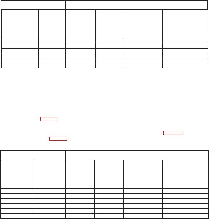
Table 5. Channel 1 Vertical Deflection Aberration Limits and Adjustments
Oscilloscope calibrator
EDGE settings
Test instrument
Aberration limits
A AND B
minor division
SEC/DIV
VOLTS/DIV
positive or
switch
Amplitude
switch
Adjustments
negative or minor
settings
settings
division pk-pk
(Ps)
<
b(83) thru (92)
10
mVpp
1 MHz
0.05
2m
1
50
mVpp
1 MHz
0.05
10
m
1
100
mVpp
1 MHz
0.05
20
m
1
250
mVpp
1 MHz
0.05
50
m
1
0.5 Vpp
1 MHz
0.05
0.1
1
1 Vpp
1 MHz
0.05
0.2
1
(18) Set VERTICAL MODE CH 1 BOTH CH 2 switch to CH 2.
(19) Remove connection located at TI CH 1 and connect oscilloscope calibrator
CHAN 1 to TI CH 2 using a 50 : feedthrough termination.
(20) Ensure CH 2 VOLTS/DIV switch is set to 2m and oscilloscope calibrator EDGE
pushbutton green LED is illuminated.
(21) Use technique of (22) below for TI settings and oscilloscope calibrator output
settings listed in table 6.
(22) Adjust CH 2 POSITION control to position top of waveform to center horizontal
graticule line.
If squarewave aberrations exceed those listed in table 6, perform
adjustments listed in table 6.
Table 6. Channel 2 Vertical Deflection Aberration Limits and Adjustments
Oscilloscope calibrator
Test instrument
EDGE settings
Aberration limits
A AND B
minor division
SEC/DIV
VOLTS/DIV
positive or
switch
Amplitude
switch
Adjustments
negative or minor
settings
settings
division pk-pk
(Ps)
<
b(93) thru (99)
10 mVpp
1 MHz
0.05
2m
1
50
mVpp
1 MHz
0.05
10
m
1
100
mVpp
1 MHz
0.05
20
m
1
250
mVpp
1 MHz
0.05
50
m
1
0.5 Vpp
1 MHz
0.05
0.1
1
1 Vpp
1 MHz
0.05
0.2
1
8