
TB 9-6625-2162-24
Table 5. Attenuation dB Adjustments - Continued
0-80 switch
Adjustments
Attenuation dB positions
40
VR6
50
VR7
60
VR8
70
VR9
80
VR10
10. Power Measurement
a. Performance Check
NOTE
Before performing (7) through (14) below, the exact output
coupling ratio of directional coupler must be determined and
recorded in accordance with (1) through (6) below.
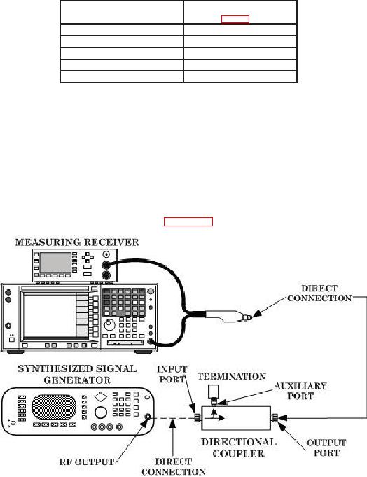
(1) Connect equipment as shown in figure 4, connection A.
Connection A
Figure 4. Directional coupler ratio check (connection A).