
TB 9-6625-2183-24
(3) Position VOLTS/DIV controls for exactly 6 divisions of vertical deflection.
(4) Remove test lead from CH1 X INPUT and connect oscilloscope calibrator
SOURCE/MEASURE CHAN 1 to CH1 X INPUT.
(5) Set oscilloscope calibrator for a 0.3 V, 1 kHz VOLTAGE mode output.
(6) Adjust oscilloscope calibrator rotary knob below EDIT FIELD button for exactly
6 divisions of vertical deflection. If oscilloscope calibrator err readout indication is not
within 1% perform b below.
b. Adjustments
(1) Set oscilloscope calibrator for a 0.3 V, 1 kHz VOLTAGE mode output.
(2) Adjust oscilloscope calibrator rotary knob below EDIT FIELD button for exactly
6 divisions of vertical display.
(3) Remove cable from CH1 X INPUT and connect CH1 X INPUT to .3V CAL
OUT jack.
(4) Adjust R61 (fig. 1) for 6 divisions of vertical display.
16. Dc Volts
a. Performance Check
(1) Connect DMM INPUT LO to HI.
(2) Press FUNCTION DCV pushbutton. If DMM indication is not within -.002 to
+.002, perform b (1) below.
(3) Connect calibrator to DMM INPUT LO and HI.
(4) Set calibrator output to indicate 1.900 V on TI. If calibrator does not indicate
between 1.8961 and 1.9039 V, perform b (2) below.
(5) Set calibrator output for DMM indications as listed in table 7. Calibrator will
indicate within settings listed.
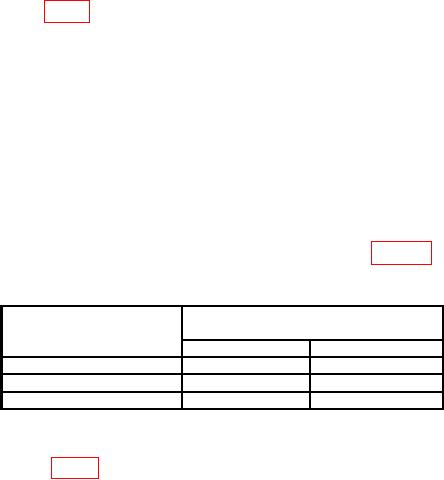
Table 7. Dc Voltage Check
Test instrument
Calibrator
DMM
indications (V)
indications
Min
Max
19.00
18.961
19.039
190.0
189.61
190.39
1000
997
1003
b. Adjustments
(1) Adjust R803 (fig. 3) for DMM indication of .000 with a flashing (minus) sign (R).