
TB 9-6625-2183-24
(6) Repeat technique of (3) and (4) above for CH2. If trace does not remain on
horizontal graticule centerline within 1.5 divisions, perform b (2) below.
b. Adjustments
(1) Adjust R102 CH1 STEP ATTEN BAL (fig. 1) (accessible without removing center
case) to align trace on horizontal graticule center line. Repeat a (3) and (4) above until no
further improvement is noted (R).
(2) Adjust R122 CH2 STEP ATTEN BAL (fig. 1) (accessible without removing case)
to align trace on horizontal graticule center line. Repeat a (6) above until no further
improvement is noted (R).
10. Vertical Gain
a. Performance Check
(1) Set switches as listed in (a) through (c) below:
(a) VOLTS/DIV to 5m.
(b) CH2 AC-GND-DC to DC.
(c) SEC/DIV to .5 m.
(2) Connect oscilloscope calibrator SOURCE/MEASURE CHAN 2 to TI CH2 input.
(3) Set oscilloscope calibrator for a channel 2, 1 kHz, 30 mV VOLTAGE mode output.
(4) Adjust oscilloscope calibrator rotary knob below EDIT FIELD for a 6 division
display. If oscilloscope calibrator err readout indication is not within 3%, perform b
(1) below.
(5) Set VOLTS/DIV and oscilloscope calibrator VOLTAGE outputs as listed in
table 4. At each setting, adjust oscilloscope calibrator rotary knob below EDIT FIELD for
6 divisions. Oscilloscope calibrator err readout indication will be within 3% at each setting.
(6) Set VOLTS/DIV switch to 5 DIV CAL. TI will indicate between 4.8 to 5.2 divisions.
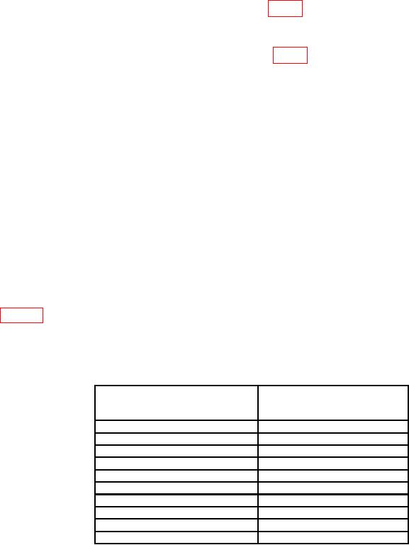
Table 4. Vertical gain
Test instrument
Oscilloscope calibrator
VOLTAGE
VOLTS/DIV switch
output
settings
10 m
60 mV
20 m
120 mV
50 m
300 mV
0.1
0.6 V
0.2
1.2 V
0.5
3 V
1
6 V
2
12 V
5
30 V
10
60 V
(7) Press CH1 TRIGGER pushbutton, set VERT MODE switch to CH1 and
connect oscilloscope calibrator SOURCE/MEASURE CHAN 1 to TI CH1 input.