
TB 9-6625-2322-24
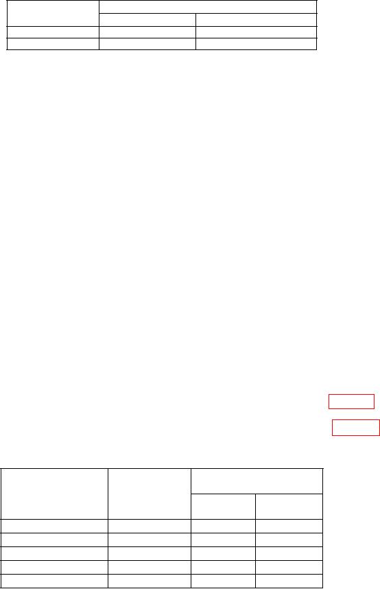
Table 10. AM Meter
Measuring receiver indication
Test
description
Min (%)
Max (%)
50% AM @ 5 GHz
45.0
55.0
Incd. PM @ 5 GHz
0.001
0.2
(9) Set measuring receiver to measure amplitude modulation, with +PEAK
detector, high pass filter to <20 Hz, and lo pass filter to >20 kHz.
(10) Press TI keys as listed in (a) through (h) below.
(a) Frequency Control, F0, Edit F0, 5, and GHz.
(b) Level Control, L0, Edit L0, 5, and dB.
(c) Modulation, AM, More, Int/Ext to select External AM Status.
(d) OUTPUT on.
(e) More, Log/Linear to display Sensitivity in dB, and Previous Menu.
(f) Front/Rear to display Source Front.
(g) 600 /50
to display Impedance 600.
(h) Edit Sens, 6, dB, and Edit Sens.
(11) Set audio analyzer controls as listed in (a) through (c) below.
(a) SOURCE FREQ to 30 Hz.
(b) SOURCE LEVEL to 1 V.
.
(c) Impedance to 600
(12) Set the measuring receiver to AM in Ratio mode.
(13) Verify that the measuring receiver indicates within limits listed in table 11.
(14) Set the audio analyzer output frequency to the values listed in table 11 and
repeat (13) above.
Table 11. External AM Frequency Response
Measuring receiver
Audio analyzer
indication
output
Test
Min
Max
description
(Hz)
(dB)
(dB)
100
Hz
Response
100
-0.3
0.3
1
kHz
Response
1000
-0.3
0.3
2
kHz
Response
2000
-0.3
0.3
5
kHz
Response
5000
-0.3
0.3
10
kHz
Response
10000
-0.3
0.3
16