
TB 9-6625-2344-35
(25) Calculate vertical gain using formula below. Calculated result will be within
limits specified in first row of table 1 below.
V avg. 2 - V avg. 1 = vertical gain
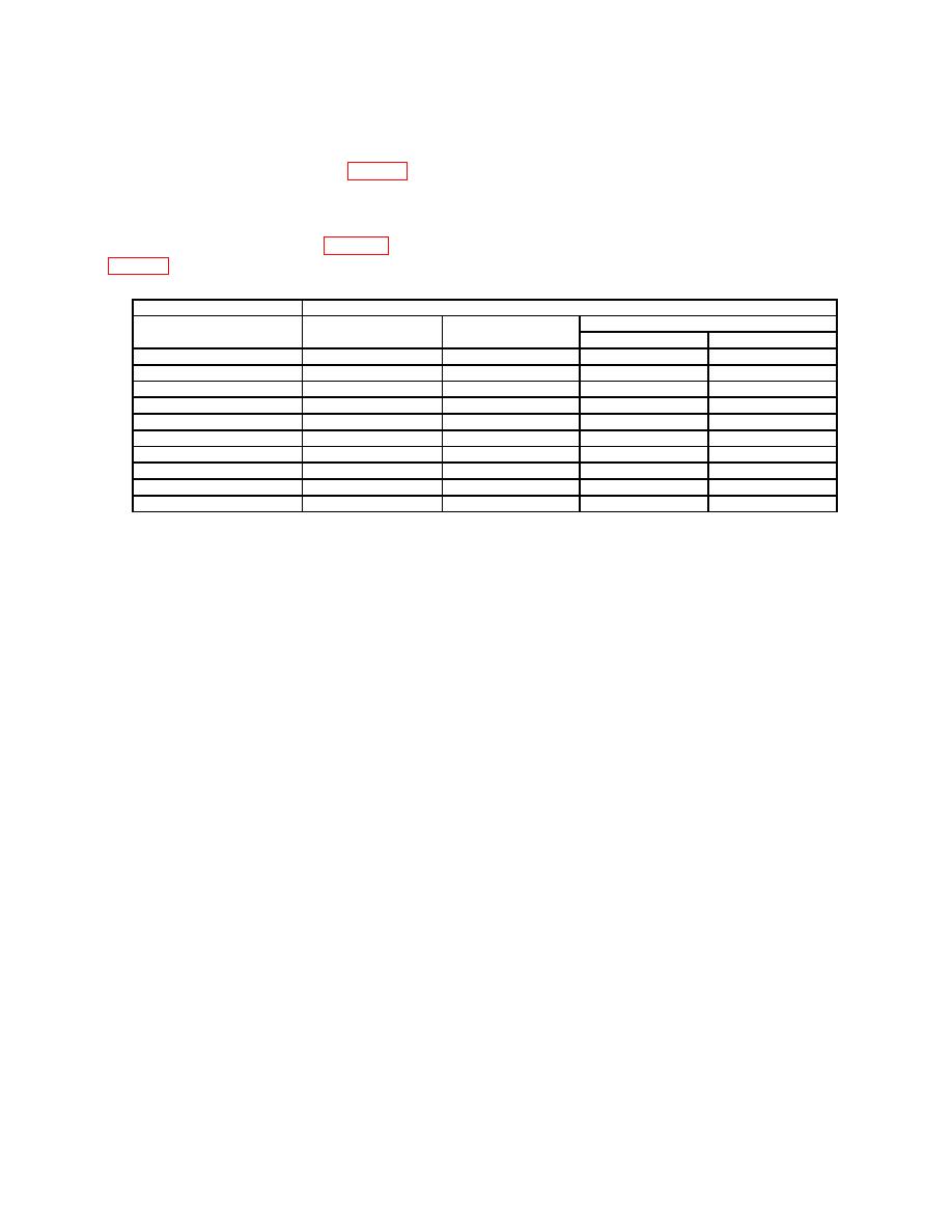
(26) Repeat technique used in (13) through (25) above for remaining TI settings and
calibrator outputs listed in table 3. Calculated results will be within limits specified in
table 3 below.
Oscilloscope calibrator
Test instrument
Scale
Calculated gain limit
Output (dc)
(/div)
Offset
Min
Max
35
V
5
V
17.5
V
34.490 V
35.510
V
14
V
2
V
7.0
V
13.796 V
14.204
V
8.75 V
1.25 V
4.375 V
8.623 V
8.887
V
3.5 V
500
mV
1.75 V
3.449 V
3.551
V
1.75 V
250
mV
875
mV
1.724 V
1.77548
V
700
mV
100
mV
350
mV
689.808 mV
710.19
mV
350
mV
50
mV
175
mV
344.904 mV
355.096
mV
140
mV
20
mV
70
mV
137.962 mV
142.038
mV
70
mV
10
mV
35
mV
68.981 mV
71.019
mV
49
mV
7
mV1
24.5
mV
48.287 mV
49.713
mV
Ranges from 1 mV to 6 mV/div are handled in firmware and will be within tolerance when the 7 mV/div range is within
1.
tolerance.
(27) Set oscilloscope calibrator to standby.
(28) Press TI buttons as listed in (a) and (b) below:
(a) VERTICAL 1 (not illuminated).
(b) VERTICAL 2 (illuminated).
(29) Change oscilloscope calibrator output from channel 1 to channel 2.
(30) Repeat technique of (9) through (29) above for remaining TI channels.
(31) Set oscilloscope calibrator to standby.
b. Adjustments. None.
9. Vertical Offset
a. Performance Check
(1) Press TI DEFAULT SETUP button.
(2) Click SETUP menu on top of TI display.
(3) From displayed drop-down menu, click ACQUISITION.
(4) In ACQUISITION SETUP window, click SAMPLING MODE EQUIVALENT
TIME and AVERAGING ENABLED box.
(5) Place cursor over # OF AVERAGES box and left click mouse to activate percent.
(6) Using either TI keyboard or mouse, enter 32 and click OK key.
