
TB 9-4931-488-24
b. Adjustments
(1) Position controls as listed in (a) through (d) below:
(a) AM X10% pushbutton pressed.
(b) AM switch to OFF.
(c) MODULATION FREQUENCY range switch to FIXED FREQ 1 kHz.
(d) AM control fully ccw.
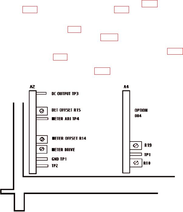
(2) Connect multimeter INPUT HI to A2TP3 (DC OUTPUT, fig. 1) and INPUT LO
to A2TP1 (GND, fig. 1). Adjust A2R15 (DET OFFSET, fig. 1) for multimeter indication of
0.000 1 mV dc.
(3) Disconnect multimeter INPUT HI from DC OUTPUT, A2TP3, and connect
INPUT HI to A2TP4 (METER ADJ, fig. 1).
(4) Adjust A2R14 (METER OFFSET, fig. 1) for multimeter indication of
0.000 1 mV dc.
(5) Disconnect multimeter INPUT HI from A2TP4 (METER ADJ, fig. 1) and
connect to A26A2TP1 (AM IN, fig. 2).
(6) Set AM switch to INT and adjust AM control for a multimeter indication of
0.707 V ac. Adjust A2R29 (METER DRIVE, fig. 1) for TI meter indication of 10 on a
0 to 10 scale.
R28
Figure 1. Test Instrument - Top Left Hand Side.
14