
TB 9-4931-488-24
NOTE
For TI's containing option 002, perform technique of (12)
through (16) below. For all others set RF OFF/ON switch to
OFF and proceed to paragraph 11 below.
(12)Press spectrum analyzer Marker [Off].
(13)Position controls as listed in (a) through (d) below.
(a) RANGE MHz switch to 1024-512 MHz.
(b) OUTPUT LEVEL switch to +10 dBm.
(c) RF OFF/ON switch to ON.
(d) COUNTER MODE EXPAND X10 pushbutton released.
(14)Adjust FREQUENCY TUNE control for a FREQUENCY MHz display
indication of 1024 MHz and OUTPUT LEVEL vernier control(s) fully cw.
(15)Set spectrum analyzer to TI frequency, set power reference Marker, Peak
Search, Marker, [Delta], then tune to harmonic frequency listed in table 4. Harmonic
frequency Mkr1 indication should be within limits listed in table 4.
(16)Repeat technique of (12) through (15) above as necessary for remaining rows in
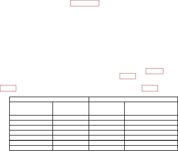
Table 4. Harmonic Distortion Accuracy (TI Containing Option 002 Only).
Test instrument
Spectrum analyzer
Tolerance
DATA amplitude
DATA frequency
limit harmonics ≥ dB below
frequency
(dBm)
(MHz)
(MHz)
fundamental
+10
1024
2048
-12
+10
1024
3072
-12
+10
1024
4096
-12
+10
1024
5120
-12
+10
1024
2048
-12
-40 1
512
256
-20
-40
512
768
-20
1 Set OUTPUT LEVEL vernier for a meter reading of +3 dB, and set spectrum analyzer attenuation to 0 dB.
(17)Set RF OFF/ON switch to OFF.
(18)On spectrum analyzer select MODE, then Measuring Receiver.
b. Adjustments. No adjustments can be made.
10