
TB 9-6625-106-24
8. Spectral Purity
a. Performance Check
(1) Connect TI 10 MHz REF OUT to EXT REF IN of the measuring receiver. Set
measuring receiver for EXT 10 MHz Reference.
(2) Set measuring receiver to spectrum analysis mode and connect RF INPUT to TI
RF Output.
(3) Press TI keys as listed in (a) through (c) below.
(a) SYSTEM, RESET.
(b) EDIT F1, 10, MHz.
(c) EDIT L1, 10, dBm.
(4) Using standard spurious signal and harmonic measurement techniques on the
for the first frequency listed in table 3 and verify that the spectrum analyzer indication is
within limits listed in table 3.
(5) Repeat (4) above for the remaining frequencies listed in table 3. Measuring
receiver will indicate within limits listed in table 3.
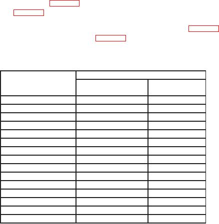
Table 3. Spectral Purity
Measuring Receiver
Test instrument
Harmonic Related
Non-Harmonic
Max ” (dBc)
Max ” (dBc)
10.0
MHz
-30
-40
15.0
MHz
-30
-40
30.0
MHz
-30
-40
45.0
MHz
-30
-40
50.0
MHz
-30
-40
50.1
MHz
-40
-40
600.0
MHz
-40
-40
1.5
GHz
-40
-40
1.991 GHz
-40
-40
2.0
GHz
-60
-60
9.99 GHz
-60
-60
10.01 GHz
-60
-60
20.0 2 GHz
-60
-60
2 GHz
20.01
-40
-60
2
24.0
GHz
-40
-60
Edit L1 to 8 dBm
1
Verify only the second harmonic and non-harmonic signals.
2
(6) Set TI outputs to minimum and disconnect the measuring receiver RF INPUT
from the RF Output of the TI.
b. Adjustments. No adjustments can be made.