TB 9-6625-116-24
(9) Set TI as listed in (a) through (h) below:
(a) Major function, AUX
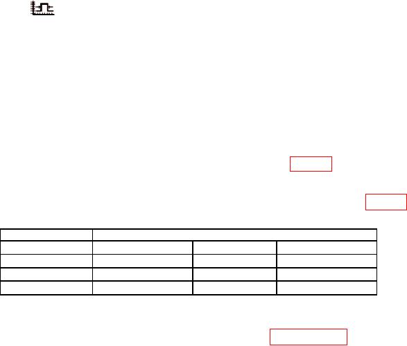
(b) [
] (pulse width)
(c) [SIGNAL CHANNEL]
(d) [SIGNAL CH 1]
(e) [EXIT]
(f) Keypad Entry, 4
(g) [nS]
(h) OUTPUT, ON
(10) Frequency counter will indicate within the limits of table 7. If not, perform b
below.
(11) Repeat technique of (9) (f) and (g) above for remaining TI outputs in table 7.
Table 7. Pulse Width Accuracy
TI
Frequency Counter
Pulse Width
Min
Measured
Max
4.0000 nS
3.6000 nS
4.4000 nS
20.000 nS
18.8000 nS.
21.2000 nS
100.00 nS
95.2000 nS
105.2000 nS
(12) Set TI OUTPUT to OFF and disconnect equipment set-up.
b. Adjustments. Perform entire alignment procedure in paragraph 11 below.
10. Load Resistance Measurement Accuracy
a. Performance Check
(1) Connect TI CH 1 output to resistance standard SENSE HI and SENSE LO
through active head.
.
(2) Set resistance standard to 50.010
(3) Set TI as listed in (a) through (f) below:
(a) Major function, AUX
(b) [ ]
(c) [SIGNAL CHANNEL]
(d) [SIGNAL CH 1]
]
(e) [LOAD 50
(f) OUTPUT, ON

