
TB 9-6625-170-24
13. Output Impedance
a. Performance Check
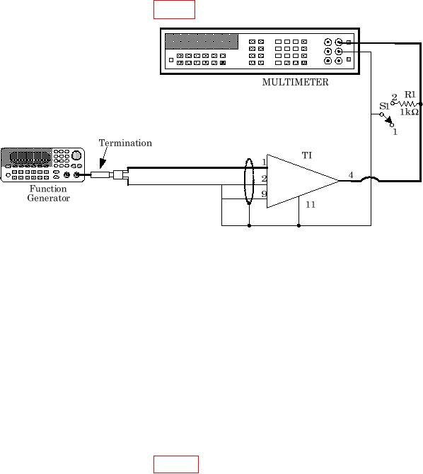
(1) Connect TI as shown in figure 5 using a watt resistor for R1.
Figure 5. Output Impedance Test.
(2) Set the GAIN switch to the desired gain and the X1/X.01 switch to X1.
(3) Set the multimeter to measure AC voltage.
(4) Adjust the function generator (and if necessary, the gain-vernier control of the
TI) for a 1.000 V rms sine wave of 100 Hz at the TI output.
(5) Set S1 to 2 or short across the resistor. Record the change in the amplifier
output voltage as e.
(6) Calculate the output resistance using the formula: Zout = 1000 * e.
(7) The output impedance should be ≤ 1 Ω.
b. Adjustments. None.
14. CMR DC Unbalance
a. Performance Check
(1) Connect TI as shown in figure 6.
(2) Set the GAIN switch to 1000. Set the calibrator for a 100 V dc output.
(3) Adjust the oscilloscope to display A only.
(4) Adjust the ZERO controls for zero output from the TI and center the trace on
the oscilloscope.
(5) Set S1 to 2.
(6) Set S2 to 2 and note the change in voltage for step (4) as e.
(7) Set S2 to 1 and S3 to 2 and again note the change in voltage from step (3) as e.