• Home
  • Download PDF
  • Order CD-ROM
  • Order in Print
Figure 1. Test instrument - adjustment locations.
Input 1 Sensitivity Test (500 MHz to 18 GHz)

Calibration Procedure For Microwave Frequency Counter, Model 5352B Option 001 Page Navigation
  1    2    3    4    5  6  7    8    9    10    11  
img
. . . .
TB 9-6625-2247-40
Figure 2. Input 2 sensitivity (50 Ω) - equipment setup.
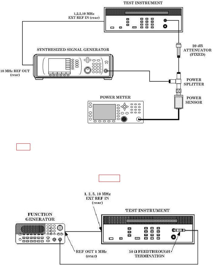
(5) Insert a 50 Ω feed through termination between INPUT 2 and 20 dB attenuator
(fixed) (fig. 2).
(6) Press 1 MΩ key on FUNCTION/DATA keyboard.
(7) Repeat technique (3) above.
(8) Repeat technique (3) above for synthesized signal generator frequency of 80 MHz.
(9) Connect equipment as shown in figure 3.
Figure 3. Input 2 sensitivity test (1 MΩ) - equipment setup.
7


Privacy Statement
Press Release
Contact

© Copyright Integrated Publishing, Inc.. All Rights Reserved.