
TB 9-4931-538-40
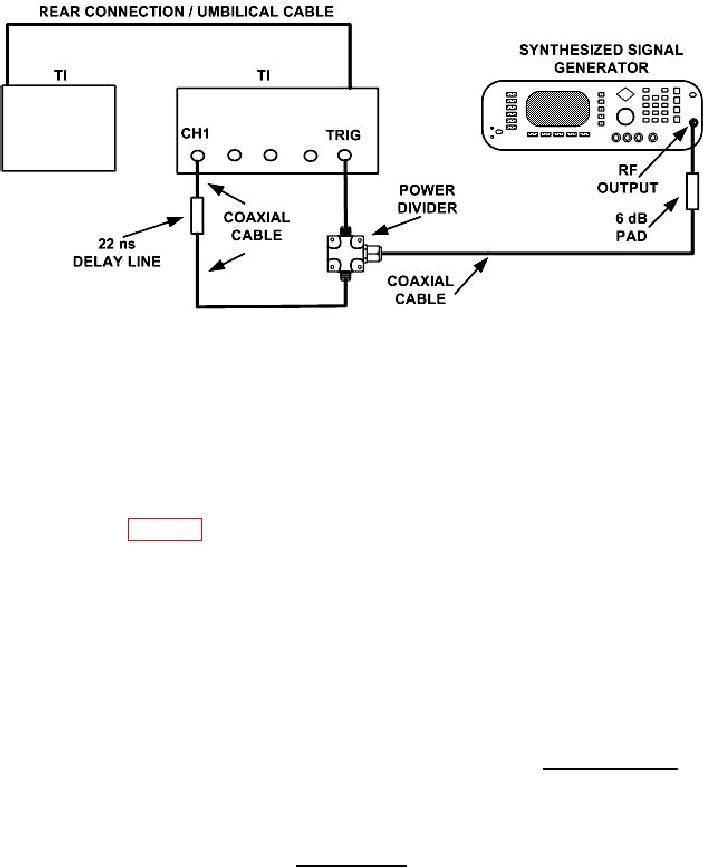
Figure 8. Trigger sensitivity jitter - equipment setup.
V p-p 200 mV as displayed on screen.
(30) Press Timebase and TIME/DIV keys and set Sweep Speed = 500 ps/div,
Delay to 22.0000 ns (see NOTE below), and Delay Ref at Center is highlighted.
NOTE
The length of the coaxial cables being used to make connections
in figure 8 must be measured, calculated, and added to the
22 ns delay line setting in (30) above. Example: Total cable
length = 6 feet. 6' x 1.6 ns = 9.6 ns. (22 ns + 9.6 ns = 31.6 ns).
point that does not expand or contract with frequency of synthesized signal generator.
(Press Display key and set Display Mode to Persist is highlighted. Pressing the
ENTRY pushbutton until Persistence = Infinite will help find the trigger.
(32) Press Delta V key. Set V Markers On and press Preset Levels key until
50%-50% is highlighted. Press the Auto Level Set key.
(33) Press Delta t key. Set T Markers On and set the start marker on the 50% point on
).
the positive slope of the selected trigger point. Record Start Position point (
(34) Press Timebase and TIME/DIV keys and set Sweep Speed = 200 ps/div, and
set DELAY to Delay = the value of the START MARKER.
(35) Adjust the delay of the TI to center the positive edge of the waveform on the
display. Record the reading (Delay =
ns).
(36) Press Timebase and TIME/DIV key and set Sweep Speed = 10.0 ps/div.
Press Channels key and set VOLTS/DIV to Sensitivity = 5 mV/div.
18