TB 9-5210-219-40
CAUTION
TI sensor contains an electronic microcircuit which can be
damaged by electrostatic discharge. Grounding wrist strap
must be worn when handling sensor and sensor must be stored
in a static protective bag. Use care not to damage sensor when
mounting sensor to angle iron.
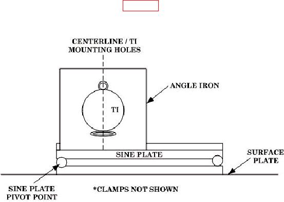
(1) Setup equipment as shown in figure 3 below with angle iron against sine plate
side rails. Position TI so the centerline of sensor mounting holes is perpendicular to sine
plate working surface.
Figure 3. Sensor setup.
(2) TI sensor must be secured to prevent movement. Lettering on sensor must be
right side up and facing technician. This is TI Direct position.
(3) Use precision level to level sine plate length and width to within 10 arc-sec.
(4) Connect TI sensor to DC power supply and set input voltage to TI to 12 V dc and
-12 V dc.
(5) Connect TI sensor output to multimeter.
(6) Adjust TI sensor orientation on angle iron until multimeter indicates -
0.006 to 0.006 V dc.
(7) Rotate angle iron 180 degrees to same location against sine plate side rails.
Lettering on sensor will remain right side up and face away from technician. This is TI
Reverse position.
(8) If multimeter does not indicate within -0.006 to 0.006 V dc adjust orientation of
TI sensor on angle iron.
(9) Alternate between TI Direct and Reverse positions within -0.006 to 0.006 V dc in
both positions.
10

