TB 9-5210-219-40
(3) Wring together a 5.736 inch gage block stack and insert into sine plate to
establish a 35 degree angle.
(4) Place an angle block equal to first corresponding size listed in table 6 for range
of TI on sine plate.
(5) Place TI on angle block. If TI does not indicate OVERRANGE, increase size of
angle block.
(6) TI must OVERRANGE when combined angle of sine plate and added angle
block are within limits specified in table 6, if not perform b below.
(7) Rotate TI 180 degrees so TI display remains right side up and facing away from
technician.
(8) Repeat technique of (4) through (6) above.
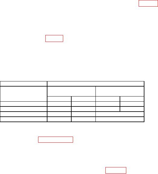
Table 6. Over Range (Alternate Method)
Angle block
Total applied angle
Limits
Limits
Size
(45 degree range)
(60 degree range)
(degrees)
Min
Max
Min
Max
15
50
60
N/A
N/A
15
-60
-50
N/A
N/A
25
N/A
N/A
>60
25
N/A
N/A
>-60
(9) Remove TI, angle block and gage blocks from sine plate.
b. Adjustments. Perform paragraph 15 below.
12. Alternate Reference and Hold
a. Performance Check
(1) If not already done, setup equipment as shown in figure 2.
(2) Ensure TI is parallel to vertical face of angle plate.
TI must be secured to
prevent movement.
(3) Set index table to 15 degrees.
(4) Press TI ALT REF button. TI will indicate ALT REF 0.0. (If the words SET
ALT REF appear after ALT REF button has been pressed, press ALT REF button again.
TI will indicate ALT REF 0.0).
(5) Set index table to 345 degrees. If TI does not indicate -30 degrees 0.5 degree
(for TI's with 45 degree range) or -30 degrees 0.1 degree (for TI's with 60 degree range),
perform b below.
(6) Press TI HOLD button. TI display must flash repeatedly. (For older models,
HOLD button must be held to enable hold function).
(7) Remove TI from index table and place it on surface plate. TI display will remain
same value as (6) above.

