
TB 9-5985-314-24
(28) Connect TI into figure 5 equipment setup as listed in (a) through (c) below:
(a) INPUT PORT 1 to POINT A.
(b) OUTPUT PORT 2 to POINT B.
(c) OUTPUT PORT 3 to 50 : termination.
(29) Record receiver system indication in OUTPUT PORT 2 column of table 8.
remaining frequency settings listed in table 8. Measure and record insertion loss for
OUTPUT PORT 2 column in table 8. Insertion loss will be approximately equal to value
listed in Appendix D.
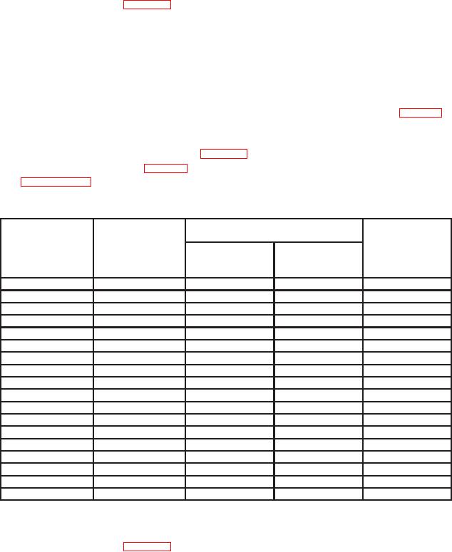
Table 8. Insertion Loss - Output Port Tracking (18 to 26.5 GHz)
Receiver system indication
OUTPUT
insertion loss
OUTPUT
OUTPUT
PORT
Programmable
Signal
PORT 2
PORT 3
TRACKING
sweep generator
generator
(GHz)
(MHz)
(dB)
(dB)
(dB)
18.000
8650
18.500
8900
19.000
9150
19.500
9400
20.000
9650
20.500
9900
21.000
10,150
21.500
10,400
22.000
10,650
22.500
10,900
23.000
11,150
23.500
11,400
24.000
11,650
24.500
11,900
25.000
12,150
25.500
12,400
26.000
12,650
26.500
12,900
(31) Repeat (24), (25), and (27) above.
(32) Connect TI into figure 5 equipment setup as listed in (a) through (c) below:
(a) INPUT PORT 1 to POINT A.
(b) OUTPUT PORT 3 to POINT B.
(c) OUTPUT PORT 2 to 50 : termination.
28