
TB 9-6625-106-24
16. Amplitude Modulation Internal
a. Performance Check
(1) Press TI keys as listed in (a) through (h) below:
(a) System, Reset.
(b) Edit L1, 4, dBm.
(c) Edit F1, 1.5, GHz.
(d) Modulation, AM, Internal/External, select Internal.
(e) Log\Linear, select Linear. (Depth displayed in %)
(f) Edit Depth, 50, %.
(g) Edit rate, 1, kHz.
(h) ON/OFF, select ON.
(2) Allow measuring receiver to tune to TI carrier frequency, then measure AM
Depth with PEAK + -/2 detector, and 300 Hz high pass and 3 kHz low pass filters.
(3) Verify that the measuring receiver indication within limits listed in table 16; if
not, perform b below.
(4) Repeat (1) (b), (c) and (2) through (3) above for the remaining output power
levels, and frequencies listed in table 16. Measuring receiver will indicate within limits
listed in table 16; if not, perform b below.
(5) Set TI outputs to minimum.
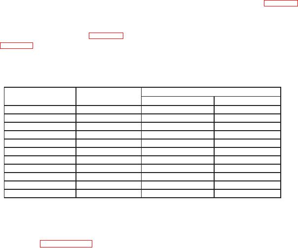
Table 16. Amplitude Modulation Internal.
Measuring receiver
TI Output Power
TI Frequency
(dBm)
(GHz)
Min (%)
Max (%)
4
1.5
45.0
55.0
2
2.2
45.0
55.0
2
2.3
45.0
55.0
2
5.0
45.0
55.0
2
8.3
45.0
55.0
2
8.4
45.0
55.0
2
14.0
45.0
55.0
2
20.0
45.0
55.0
-6
23.0
45.0
55.0
-6
26.5
45.0
55.0
-6
30.0
45.0
55.0
b. Adjustments
(1) Interface the instrument controller to the TI by performing the initial setup
procedure listed in paragraph, 7 a through c.
(2) Using a BNC tee, connect the function generator OUTPUT to the AM IN
connector of the TI and to the multimeter INPUT.
(3) Connect the sensor module (opt 550) to the RF Output of the TI. Set measuring
receiver to measure RF power at 1 GHz.